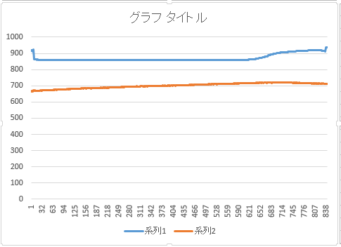
昨日PM6:30頃から今朝AM8:30頃までロガーを動かし続けた結果です。microSDカードを抜いてExcelで処理しました。
青が照度、赤が温度です。深夜は真っ暗で照度に変化がなく、朝から徐々に明るくなっています。温度は徐々に変化がありますが、センサーが基板に近いところにあるので気温とイコールではないのでしょう。
普通の人は照度を絶対値で言われてもピンとこないと思いますが、温度は絶対値がないと面白くないですね。
Self-powered Internet of Things
昨日PM6:30頃から今朝AM8:30頃までロガーを動かし続けた結果です。microSDカードを抜いてExcelで処理しました。
青が照度、赤が温度です。深夜は真っ暗で照度に変化がなく、朝から徐々に明るくなっています。温度は徐々に変化がありますが、センサーが基板に近いところにあるので気温とイコールではないのでしょう。
普通の人は照度を絶対値で言われてもピンとこないと思いますが、温度は絶対値がないと面白くないですね。

Arduinoにはアナログセンサーが直結できるので、試しに手持ちのCdsとサーミスタを繋いで、「SD記録機能付き簡易照度&温度計」にしてみました。
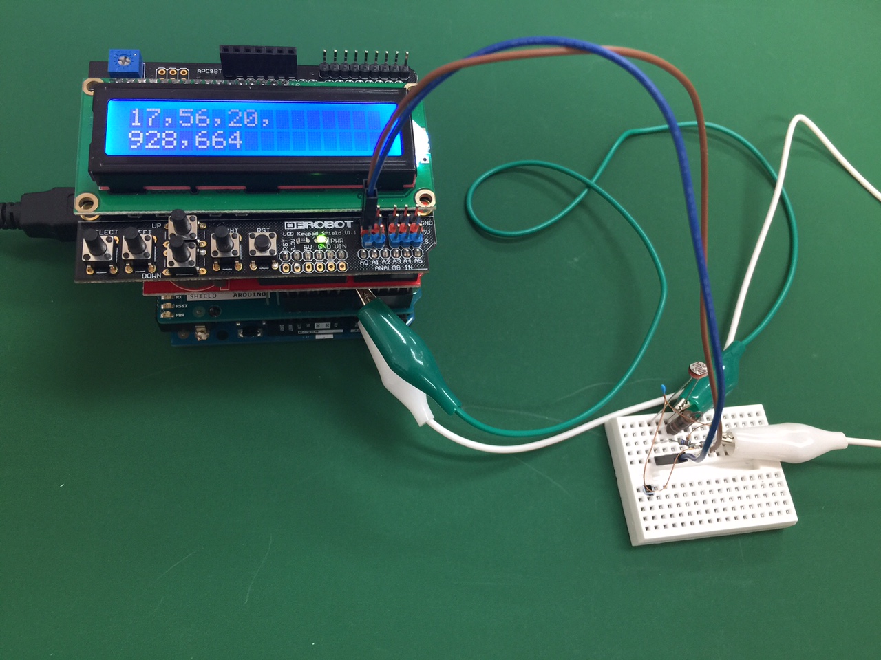
LCDの2行目、左がCds、右がサーミスタ、の読み取り値です。このまま放置して明日SDカードの中身をチェックすることにします。
エナジーハーベスト関連の仕事をしていると、電池との比較を考えないわけには行きません。
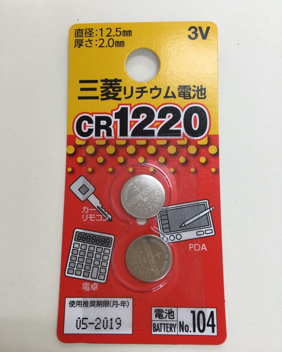
つい昨日もRTCバックアップ用のコイン型電池が切れているのがわかって電池を購入せざるを得なくなり、エナジーハーベストと電池の違いに思いを巡らせることになりました。
下が今さっき100均で購入してきたコイン型電池。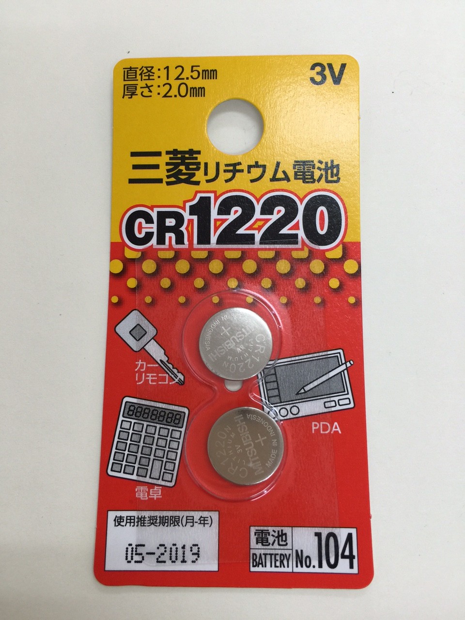
最初に目に入ったのは使用推奨期限が2019年5月となっていること。なので4年後のことをいろいろ想像してみました。
4年後以降、機械が正常に動作するかどうかも大事だが、それよりも自分が使おうとするかどうかが重要なファクターだと思われます。
使っていることを忘れる、忘れるべき、忘れていい、ようなものなのか。今の時点で4年後以降も使いたいとは思っているものの4年経ったら電池交換せずに機械全体を買い換える、買い足す、ことでもいいのかどうか。
また、仮に4年後以降もその機器を使い続けたいとして、同じタイプの電池は入手できるのか。4年くらいなら大丈夫そうにも思うが誰も保証はしてくれまい。
機械の性格にもよると思うが考える要素は沢山ありそうです。
これからはこんなことを断片的に書いていこうと思っています。
TIPSを紹介しましょう。そう言えば最近”TIPS”って表現をあまり見かけませんね。コツ、豆知識、小技、と思ってください。
実は全く同じハードウェアを2セット使って開発を進めています。ハードウェアはソフトウェアと違って物理的な不具合(組立・配線不良、劣化・故障、等々)を考慮しておかないといけないので、ソフトウェアを同じにしたとき挙動が違えばハードウェアに何か問題があることがわかります。
あと、完成した暁に一個を実用・実証実験用、もう一個を動かなくなったときのバックアップ・動作検証用として使うためです。一個を実用として動作させながら、ソフトウェアをアップデートするとき事前に動作チェックする際にも使います。
ハードウェアが安くなったおかげで理想の開発環境が得られています。

いよいよRTC, SD, LCD、3つのシールドを全部使ってみます。
RTCとセンサー値をLCDに表示しつつSDに書き込む動作をすると3つのシールドを全て使うことになります。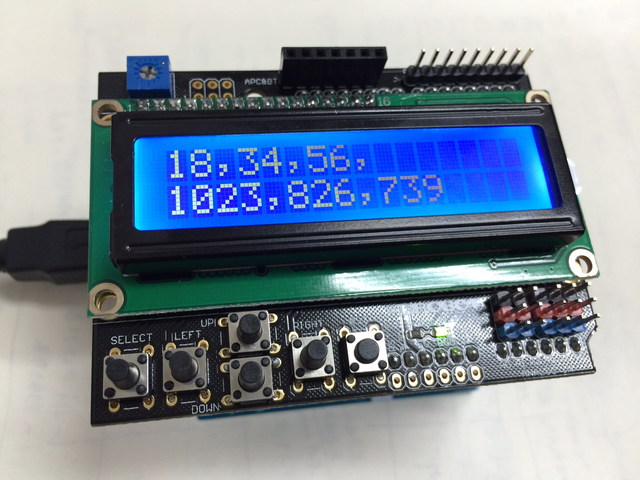
LCDに表示されている18,34,56は時、分、秒、1023,826,739はアナログ値3つを示しています。
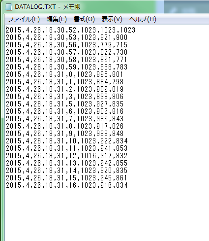
microSDを抜いてPCで中を見ると、年、月、日、時、分、秒、センサー値3つ、がそれぞれカンマ区切りで保存されているのがわかります。後でExcelで処理しやすいようにcsv形式にしました。
今日はここまで。
RTCのバッテリーバックアップに問題がありそう。昨日電源オフして帰宅したが今日電源オンしたら日時が初期値に戻っている。
調査する時間が惜しいのでブランド品で代替することを検討する。電源を入れっぱなしもしくは短時間切っても使えているので開発はこのまま進める。
4/27追記)バックアップ用電池CR1220をテスタで当たると3V程度はあるはずのところが0.5Vしかなかった。ずいぶん在庫期間が長かったようだ。交換してしばらく様子を見ることにした。
以降、複数シールドの連動を考えます。
では一番簡単と思われる時計から。RTCを読んでLCDに表示するだけです。
===apr25d
/*******************************************************
hardware test sketch
shield#1:Wireless SD
shield#2:data logger(RTC)
shield#3:LCD & keypad
Toshiyuki Hattori, 25/April 2015
********************************************************/
/*******************************************************
shield#2 RTC
Date and time functions using a DS1307 RTC connected via I2C and Wire lib
********************************************************/
#include <Wire.h>
#include “RTClib.h”
RTC_DS1307 RTC;
/*******************************************************
shield#3 LCD
********************************************************/
#include <LiquidCrystal.h>
// select the pins used on the LCD panel
LiquidCrystal lcd(8, 9, 4, 5, 6, 7);
/*******************************************************
setup section
********************************************************/
void setup()
{
/*******************************************************
shield#3 LCD
********************************************************/
lcd.begin(16, 2); // start the library
lcd.setCursor(0,0);
lcd.print(“Start “); // print a simple message
/*******************************************************
shield#2 RTC
********************************************************/
Wire.begin();
RTC.begin();
if (! RTC.isrunning()) {
lcd.print(“RTC NOT running!”);
// following line sets the RTC to the date & time this sketch was compiled
// uncomment it & upload to set the time, date and start run the RTC!
//RTC.adjust(DateTime(__DATE__, __TIME__));
}
}
/*******************************************************
loop section
********************************************************/
void loop()
{
DateTime now = RTC.now();
lcd.setCursor(0,0); // move to the beginning of the first line
lcd.print(now.year(),DEC);
lcd.print(‘/’);
lcd.print(now.month(),DEC);
lcd.print(‘/’);
lcd.print(now.day(),DEC);
lcd.print(” “);※2
lcd.setCursor(0,1); // move to the beginning of the second line
lcd.print(now.hour(),DEC);
lcd.print(‘:’);
lcd.print(now.minute(),DEC);
lcd.print(‘:’);
lcd.print(now.second(),DEC);
lcd.print(” “);※2
}
===
※2の注
RTCの読み出し値がゼロサプレスされる(例えば1月が01月とはならない)ため、前の表示が残っていると数値が乱れるのを防ぐため、表示後空白をプリントするようにしています。が、Wordpressに貼り付けると複数の空白が1つになるようで、上記ソースをコピペする際には気をつけてください。Wordpressにはダブルクオーテーションが化ける問題もあるようです。いずれ正しくダウンロードできるようにします。
RTCを手に入れて初めて使う際にはソースの※1の部分のコメントを外してRTCの初期設定をする必要があります。
年/月/日
時:分:秒
が表示されています。
最後のシールド#3、LCD&keypadシールドのテスト用スケッチです。
===sketch_apr25c_lcd
//Sample using LiquidCrystal library
#include <LiquidCrystal.h>
/*******************************************************
This program will test the LCD panel and the buttons
Mark Bramwell, July 2010
********************************************************/
// select the pins used on the LCD panel
LiquidCrystal lcd(8, 9, 4, 5, 6, 7);
// define some values used by the panel and buttons
int lcd_key = 0;
int adc_key_in = 0;
#define btnRIGHT 0
#define btnUP 1
#define btnDOWN 2
#define btnLEFT 3
#define btnSELECT 4
#define btnNONE 5
// read the buttons
int read_LCD_buttons()
{
adc_key_in = analogRead(0); // read the value from the sensor
// my buttons when read are centered at these valies: 0, 144, 329, 504, 741
// we add approx 50 to those values and check to see if we are close
if (adc_key_in > 1000) return btnNONE; // We make this the 1st option for speed reasons since it will be the most likely result
// For V1.1 us this threshold
if (adc_key_in < 50) return btnRIGHT;
if (adc_key_in < 250) return btnUP;
if (adc_key_in < 450) return btnDOWN;
if (adc_key_in < 650) return btnLEFT;
if (adc_key_in < 850) return btnSELECT;
// For V1.0 comment the other threshold and use the one below:
/*
if (adc_key_in < 50) return btnRIGHT;
if (adc_key_in < 195) return btnUP;
if (adc_key_in < 380) return btnDOWN;
if (adc_key_in < 555) return btnLEFT;
if (adc_key_in < 790) return btnSELECT;
*/
return btnNONE; // when all others fail, return this…
}
void setup()
{
lcd.begin(16, 2); // start the library
lcd.setCursor(0,0);
lcd.print(“Push the buttons”); // print a simple message
}
void loop()
{
lcd.setCursor(9,1); // move cursor to second line “1” and 9 spaces over
lcd.print(millis()/1000); // display seconds elapsed since power-up
lcd.setCursor(0,1); // move to the begining of the second line
lcd_key = read_LCD_buttons(); // read the buttons
switch (lcd_key) // depending on which button was pushed, we perform an action
{
case btnRIGHT:
{
lcd.print(“RIGHT “);
break;
}
case btnLEFT:
{
lcd.print(“LEFT “);
break;
}
case btnUP:
{
lcd.print(“UP “);
break;
}
case btnDOWN:
{
lcd.print(“DOWN “);
break;
}
case btnSELECT:
{
lcd.print(“SELECT”);
break;
}
case btnNONE:
{
lcd.print(“NONE “);
break;
}
}
}
===
これを実行してLCDに表示され、キーを押したとき表示が変われば正しく動作しています。
左のキーを押したら”NONE”が”LEFT”に変わりました。
シールド#2のデータロガーシールドのテスト用スケッチです。
===sketch_apr25b_rtc
// Date and time functions using a DS1307 RTC connected via I2C and Wire lib
#include <Wire.h>
#include “RTClib.h”
RTC_DS1307 RTC;
void setup () {
Serial.begin(57600);
Wire.begin();
RTC.begin();
if (! RTC.isrunning()) {
Serial.println(“RTC is NOT running!”);
// following line sets the RTC to the date & time this sketch was compiled
// uncomment it & upload to set the time, date and start run the RTC!
//RTC.adjust(DateTime(__DATE__, __TIME__));
}
}
void loop () {
DateTime now = RTC.now();
Serial.print(now.year(), DEC);
Serial.print(‘/’);
Serial.print(now.month(), DEC);
Serial.print(‘/’);
Serial.print(now.day(), DEC);
Serial.print(‘ ‘);
Serial.print(now.hour(), DEC);
Serial.print(‘:’);
Serial.print(now.minute(), DEC);
Serial.print(‘:’);
Serial.print(now.second(), DEC);
Serial.println();
Serial.println();
delay(2000);
}
===
初めて動かすとき、RTC.adjust(…の部分のコメントを外してコンパイル&ゴーでRTCに正しい時刻を植え付ける必要があります。次にコメントアウトしてコンパイル&ゴーすれば今度は正しい時刻が表示されるはずです。
シールド#1のWireless SD shieldのテスト用スケッチです。
===sketch_apr25a_sd
/*
SD card test
This example shows how use the utility libraries on which the’
SD library is based in order to get info about your SD card.
Very useful for testing a card when you’re not sure whether its working or not.
The circuit:
* SD card attached to SPI bus as follows:
** UNO: MOSI – pin 11, MISO – pin 12, CLK – pin 13, CS – pin 4 (CS pin can be changed)
and pin #10 (SS) must be an output
** Mega: MOSI – pin 51, MISO – pin 50, CLK – pin 52, CS – pin 4 (CS pin can be changed)
and pin #52 (SS) must be an output
** Leonardo: Connect to hardware SPI via the ICSP header
Pin 4 used here for consistency with other Arduino examples
created 28 Mar 2011 by Limor Fried
modified 9 Apr 2012 by Tom Igoe
*/
// include the SD library:
#include <SPI.h>
#include <SD.h>
// set up variables using the SD utility library functions:
Sd2Card card;
SdVolume volume;
SdFile root;
// change this to match your SD shield or module;
// Arduino Ethernet shield: pin 4
// Adafruit SD shields and modules: pin 10
// Sparkfun SD shield: pin 8
const int chipSelect = 4;
void setup()
{
// Open serial communications and wait for port to open:
Serial.begin(9600);
while (!Serial) {
; // wait for serial port to connect. Needed for Leonardo only
}
Serial.print(“nInitializing SD card…”);
// On the Ethernet Shield, CS is pin 4. It’s set as an output by default.
// Note that even if it’s not used as the CS pin, the hardware SS pin
// (10 on most Arduino boards, 53 on the Mega) must be left as an output
// or the SD library functions will not work.
pinMode(SS, OUTPUT);
// we’ll use the initialization code from the utility libraries
// since we’re just testing if the card is working!
while (!card.init(SPI_HALF_SPEED, chipSelect)) {
Serial.println(“initialization failed. Things to check:”);
Serial.println(“* is a card is inserted?”);
Serial.println(“* Is your wiring correct?”);
Serial.println(“* did you change the chipSelect pin to match your shield or module?”);
}
// print the type of card
Serial.print(“nCard type: “);
switch(card.type()) {
case SD_CARD_TYPE_SD1:
Serial.println(“SD1”);
break;
case SD_CARD_TYPE_SD2:
Serial.println(“SD2”);
break;
case SD_CARD_TYPE_SDHC:
Serial.println(“SDHC”);
break;
default:
Serial.println(“Unknown”);
}
// Now we will try to open the ‘volume’/’partition’ – it should be FAT16 or FAT32
if (!volume.init(card)) {
Serial.println(“Could not find FAT16/FAT32 partition.nMake sure you’ve formatted the card”);
return;
}
// print the type and size of the first FAT-type volume
uint32_t volumesize;
Serial.print(“nVolume type is FAT”);
Serial.println(volume.fatType(), DEC);
Serial.println();
volumesize = volume.blocksPerCluster(); // clusters are collections of blocks
volumesize *= volume.clusterCount(); // we’ll have a lot of clusters
volumesize *= 512; // SD card blocks are always 512 bytes
Serial.print(“Volume size (bytes): “);
Serial.println(volumesize);
Serial.print(“Volume size (Kbytes): “);
volumesize /= 1024;
Serial.println(volumesize);
Serial.print(“Volume size (Mbytes): “);
volumesize /= 1024;
Serial.println(volumesize);
Serial.println(“nFiles found on the card (name, date and size in bytes): “);
root.openRoot(volume);
// list all files in the card with date and size
root.ls(LS_R | LS_DATE | LS_SIZE);
}
void loop(void) {
}
===
これを実行してコンソールに表示がされればSDカードは動作しています。